This article was originally written by Eaton
Pump Jacks
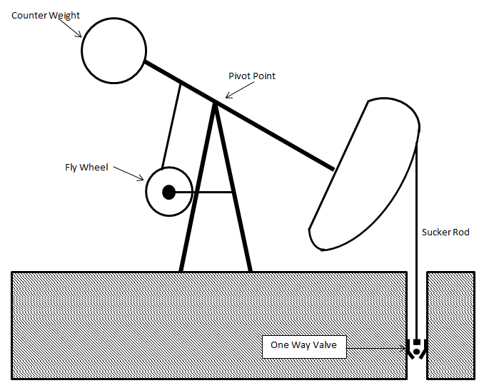
Pump Jacks (aka. Beam Pumps) are used to mechanically pump oil from a well when the pressure in the well is not high enough to force the oil to the surface. These machines operate in the same fashion as a teeter-totter with a weight and a counterweight. On one side is a metal “sucker rod” which can extend roughly 3km into the earth. On the other side is a large counterweight to offset the weight of the sucker rod head and oil. At the end of the sucker rod, there is a one-way valve that traps the oil and forces it to rise through tubing as the counterweight descends and the sucker rod rises. This concept is shown in the figure below in which the load on the motor is cyclic because of the nature of the beam pump design.
Counterweights
Counterweights are sized for each installation and are designed to maintain as constant a load as possible on the motor. To explain this further, let us consider a pump application where the reservoir is very full and has a high head pressure when it is initially drilled. The counterweight is sized so that when pumping begins, the motor must provide maximum torque while lifting the counterweight and minimum torque when the sucker rod is being lifted. This is because there is a higher oil level in the reservoir and it is easier to extract. As the well begins to be drained, there will be a period where the motor will deliver constant, or near-constant torque while lifting both the sucker rod and the counterweight. Finally, as the reservoir begins to run dry, the motor will have to deliver the most torque while lifting the sucker rod and the least amount of torque while lifting the counterweight. The conditions described here are not indicative of every installation but are merely presented here to describe how a counterweight is sized to try to maintain constant motor torque.
Motor Slip Basics
To understand the unique role that drives can play in this kind of application, it is very important to understand the concept of motor slip. Motors are designed to operate at one fixed speed — synchronous speed. Synchronous speed is determined by the number of poles and the driving frequency of the motor.
Induction motors exhibit a phenomenon known as slip, or percent slip, where speeds are below
synchronous speed. This difference in speed occurs when the motor begins to deliver torque to the load.
Standard NEMA A, NEMA B, and NEMA C motors are designed to operate between 1 to 5% slip. As
percent slip increases for these motors, we will quickly end up on the left side of the hump of the percent slip vs. percent torque curve. When this happens, torque will drop off as percent slip increases and the motor will produce less torque per amps.
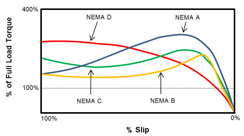
Motors designed to have percent slips between 8 to 13% slip fall into the NEMA D category. As slip increases for these motors, the torque will continue to increase until we have maximum torque at 100% slip. As a result, NEMA D motors have increasing torque per amps as they move from synchronous rotation to a locked rotor state (i.e., high starting torque). This however, comes at a cost as these motors are typically 2 to 3 times the price of their low slip counterparts.
Motors and Pump Jacks
NEMA A, NEMA B, and NEMA C are also “very responsive” with the torque they deliver. What this
means is that as soon as the motor begins to change its slip, it delivers high torque. This is good for
many applications, but not for pump jacks. Pump jacks can experience mechanical failure, valve wear,
fluid inconsistencies, and many other events that can change the load on the motor. Motors that are
“very responsive” can provide too much torque and break components like the sucker rod. NEMA D motors on the other hand provide “sloppy torque” where their slip can change without the motor delivering large amounts of torque to the load. This prevents damaging pump mechanical components.
Additionally, a NEMA D motor is often used to account for the cyclical nature of the load in beam pump applications. The high slip motor can provide torque across the full range of speeds, i.e., “sloppy torque”. And, it can “iron out” the inherent load peaks and valleys specific to pump jack applications. This harkens back to the example outlined earlier with sizing the counterweight to attain a more constant torque profile for the pump jack over the lifetime of the well.
Drives and Pump Jacks
Drives can be utilized to make NEMA B motors of the same size horse-power act as the NEMA D motors that would normally be used. This is done by varying the driving frequency so that the motor can deliver torque across a wide range of speeds. To not damage the sucker rod on the down stroke, Eaton drives utilize resistive braking to slow down the descent of the sucker rod. In addition, there are several other aspects of pump jack operation and preventative maintenance for which drives offer unique solutions.
Any downtime is very costly for pump jack operators. Some examples and their remedies are listed below.
- Sucker rods can break from cyclic fatigue and deteriorating operating conditions in the well. If the sucker rod breaks, then the oil column will not be lifted and the counter-weight will be too large for the motor to lift. This can lead to motor burn-out and large replacement costs. To remedy this, torque limits can be set to stop the motor and prevent unnecessary wear.
- Valves can become worn or filled with sediment. This can be caused by wells beginning to run dry or the oil reservoir containing high amounts of sand. In these situations, the valve will act as a viscous damper and leads to very high inefficiencies. This situation can be detected and remedied by setting trip points for motor and drive operation.
- A third situation can arise where the oil level inside the well drops to the level of the one-way valves. This is caused either by pumping the oil too rapidly or by an empty reservoir. This situation gives rise to destructive vibrations and a sharp drop in efficiency. This condition can be detected and pumping can be stopped using the control system of a drive.